Analysis3D
Your Finite Element Analysis
Software Solution
Blog
Analysis3D: A Straight‐forward and Powerful Software for Structural Steel Truss and Frame Analysis
Sometimes, it is great to come across a simple but powerful structural analysis program, where you can quickly download the program and model and analyze a structure. This is where Analysis3D comes in.
Analysis3D is a user‐friendly finite element structural analysis software for structural steel frames and trusses. The program is small in size so it downloads rapidly and has an interface that is straight‐forward so there is little to no learning curve for learning the software’s functions.
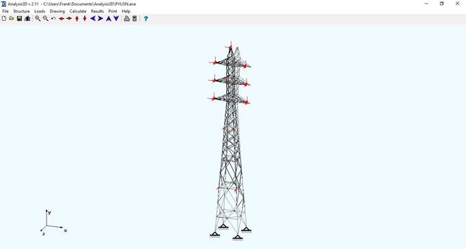
Even though Analysis3D is small in size, the software is capable of performing sophisticated analysis for 2D and 3D steel trusses and frames, including optimizing member design. Let’s explore the different functions that Analysis3D provides.
Basic but Special Functions
One special function that Anaylsis3D provides is the function to combine your new loaded data with an old structural model. You can just combine your old and new models with this simple Combine function.
Moreover, if you have an existing DXF file and you want to use that for analysis, you can simply use the Import function to import a DXF file to Analysis3D. You can also use the Export function to export your current model into a DXF file, so that you can easily manipulate your structure on AutoCAD.
Structural Data Input in Organized Tabular Forms and on the Interactive Model
Structural data, such as joint coordinates, can be inputted directly into organized tables and via the display showing the model. The COPY function helps you to conveniently replicate or move your joints over a specified distance and direction. To add new joints on the model interactively, you can double click on the location that you want your joint to be and add a new joint coordinate. You can double click on existing joints, when you want to change or remove existing joints.
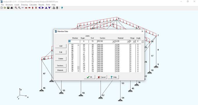
Members can be added by entering their begin and end joint numbers, section sizes, material properties, hinge conditions, and rotation angles. You can also customize member rotations based on their rotational angles around the local x‐axis. If you are ever confused about the local coordinate system of your selected member, Analysis3D shows the local coordinate system of that member when you click on it.
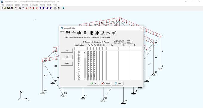
When you have your members modelled, you can then specify your support conditions. If you also happen to forget your support conditions, you can click on any of the 10 support condition images to determine which degree of freedom(s) is retrained in a specific support condition. For example, if I wanted a pinned support, I can click on the 3rd image. Once I clicked on the image, “R” (Restrained) appears in Rx, Ry, and Rz conditions and not for Mx, My, and Mz, indicating that translation is restricted in the Global X, Y, and Z direction and rotation is allowable in the Global X, Y, and Z direction. Analysis3D really guides you on your design journey!
Preset and Customizable Cross Sections and Material Properties
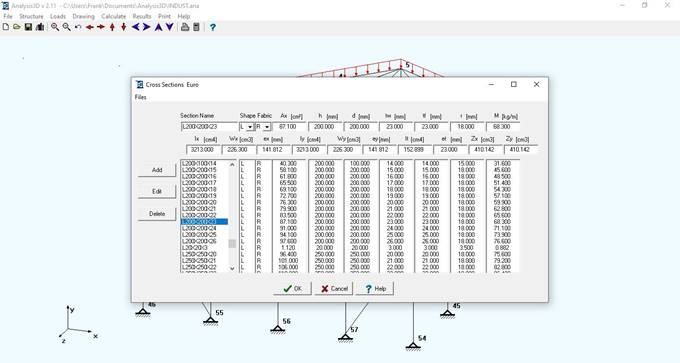
Analysis3D includes a comprehensive library of commonly used structural steel cross sections, including sections from US AISC, UK British Steel, Eurocode, Australia and New Zealand, China GB, Russia GOST, India BIS, Japan JIS and even Timber. You can easily update the library by customizing and adding your own cross-sectional properties.
Loads
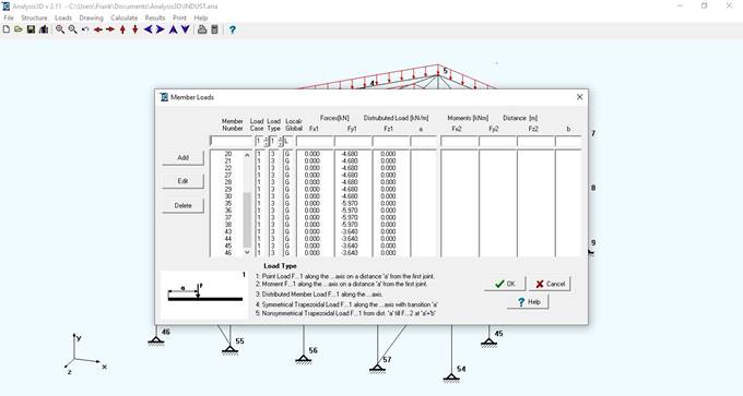
Joint and member loads can be specified. For member loads, there are 5 different types of loads that you can input; point loads, moments, distributed loads, symmetrical trapezoidal distributed load, or non‐symmetrical trapezoidal distributed load. These load types are also displayed in the program, as shown below.
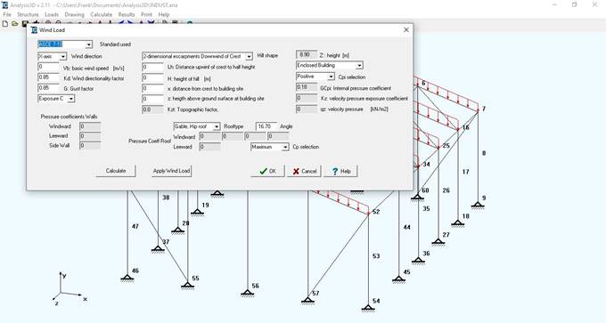
Analysis3D also includes the option to calculate and add wind loads, snow loads and seismic loads according to different standards: Eurocode and ASCE 7-16.
You can create load combinations, with a maximum of 9 different load cases, so each Load Case can have a different Load Factor. Temperature loads are also included to reflect changes in surrounding temperature, which cause thermal stresses onto structural members.
Report‐Friendly Structural Analysis Software
Analysis3D has several display options to help you better visualize and interpret the structure and the results.
Calculation and Analysis Function
Analysis3D also offers you the possibility to perform sway analysis and execute 2nd order or nonlinear calculations.
Here are the different analysis results created for consultation:
‐ Joint Displacement: Displacement values are displayed at each joint of your structural elements.
‐ Member forces and stresses: Analysis3D displays axial stresses, shear stresses, bending stresses, torsional stresses, and resulting stresses (to be compared to yield strength).
‐ Buckling: In the Buckling calculation function, Analysis3D computes members’ slenderness, slenderness limit, maximum and design buckling stress, and maximum admissible buckling load values.
‐ Reactions at supports
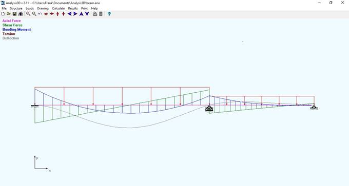
‐ Detailed Forces and Stresses for each member: Analysis3D calculates Axial forces, Shear forces, Torsion, and Bending Moments values at various locations for each member. Deflection values are also calculated. You can also view these members’ detailed forces graphically as shown above.
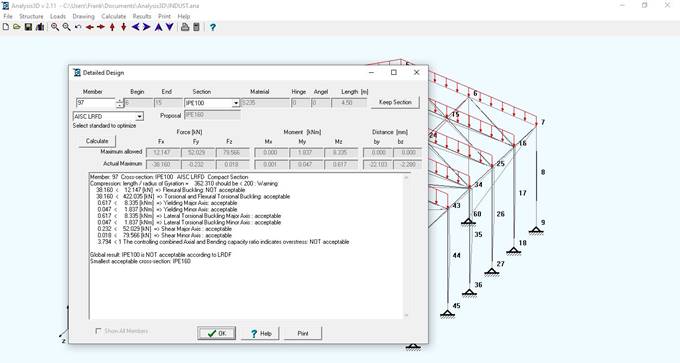
Optimization of Steel Members
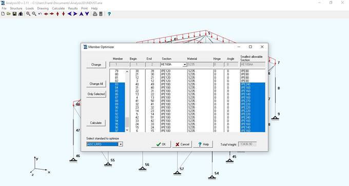
Analysis3D has a “Member Design” function that optimizes structural design by proposing the smallest allowable section that can support the load and support conditions in your model. Therefore, this optimization function can help minimize costs and increase safety in your structural design. If a member fails to support the conditions of your design, Analysis3D will propose the smallest cross‐section to resist the force and moment values. On the other hand, when a member is over designed, Anaylsis3D will propose a cross section that has the minimum area Ax to resist your forces and moments.
You can choose from 5 different detailed design methods for your optimizing your calculation; AISC-ASD, AISC-LRFD, BS5950, CISC94 and EuroCode 3 standard.
– Detailed Member Design: Analysis3D shows you the full detail of the calculations of the optimization using the selected standard. The software compares whether the designed forces and moments are acceptable to the maximum allowable forces and moments for the steel section used.
The design calculates the following criteria depending on the standard used (AISC-ASD, AISC-LRFD, BS5950, CISC94 or EuroCode 3 standard):
- Tension or compression resistance
- Bending moment (major and minor axis)
- Shear resistance
- Reduced plastic shear resistance
- Compression buckling
- Reduced moment resistance
- Reduced plastic moment resistance
- Lateral torsional buckling
- Combined bending and axial compression
- Maximum deflection in major and minor axis direction
Overall
Anaylsis3D is a Straight‐forward and Powerful Software for Structural Steel. It is a powerful and convenient software for structural analysis of steel trusses and frames. It is different from other complex structural analysis software due to its more user-friendly interface, straightforward and concise functions, and fast analysis speed.
Cuylaerts Engineering offers a FREE version download of Analysis3D for educational and non‐commercial purposes for you to download.